I keep looking at this picture and its driving me crazy. How can the smaller circle travel the same distance when its circumference is less than the entire wheel?
I keep looking at this picture and its driving me crazy. How can the smaller circle travel the same distance when its circumference is less than the entire wheel?
the smaller wheel does not just rotate, but also slides. If you had cogwheels instead of smooth wheels, you'd notice that movement is not possible.
That picture confuses things by making it look as though the red line is being "unwound" from the circle like paper towel being unwound from a roll. Our brains pick up on that, since it is a real-world example.
Both circles complete a single revolution, and both travel the same distance from left to right. If these really were rolls of paper towel, the smaller roll would have to spin faster (and therefore complete more than one full revolution) in order to lay out the same length of paper towel as the larger roll. Alternatively, if the two rolls were spinning at the same rate, the free end of the strip of towel left behind by the smaller roll would also move to the right.
In short, the image is a kind of optical/mental illusion, and you're not going crazy :)
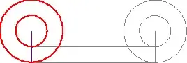
As e.James mentions, the amount of red line laid out by the inner wheel is twice the circumference of the inner wheel. So the impression that the inner wheel is rolling out the red line is an illusion. In actuality, the inner wheel slips as it rolls out the red line. The slippage is hard to see since the only fixed reference that appears on the inner wheel is its radius that follows its rotation, and its radius only comes near the line on which the wheel is rolling at the ends of the line.
I have isolated the inner wheel and placed a second wheel just below it which actually rolls out a red and green line in a proper length-for-length manner. Watching the two together, makes the slippage more noticeable.
${\hspace{4cm}}$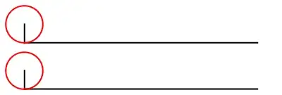
If the two circles are fixed, then they will be traveling the same difference, but at different velocities.
In fact, the ratio of the radii is equal to the ratio of the velocities a point on either circle will be traveling.
If you tried to repeat this by putting two different-sized circles on a track and making them spin to come out to be the same distance with the same angular velocity, you will notice that one of the circles will have to slide/slip along the track in order to keep them at the same pace.
Have two cylindrical wheels spin on an axle which passes through their centers. Draw a line vertical to the axle. At the point of the intersection of the line with the two wheels tie on each point a ball of string. After one revolution the lengths of string on each cylindrical wheel are different and proportional to the radius of the wheels.
Imagine this as a wheel on a car the red line in this case is the distance the car has moved forward for one rotation of the tyre. The hubcap has moved forward by the same amount. Both wheel and hubcap have performed one rotation yet a spot on the outer edge of the hubcap will have moved a shorter distance through space than a point on the tread related to the circumferential difference between tyre and hubcap.
From a physical point of view, the usual animation is misleading because it omits the wheels slippage. The animation below reflects what would happen in practice.
If the smaller circle doesn't slide, then it "pushes" the larger circle; in this case, the larger circle slides and therefore unwinds faster (third picture).
If the larger circle does not slide, then it "pulls" the smaller circle; in this case, the smaller circle slides and therefore unwinds more slowly (fourth picture).

Remark: The rigorous proof that one of the wheels certainly slides can be seen here.
Look at the path traced by each contact point between a circle and its red line. The larger wheel's point traces a much longer path from its starting point to its finishing point. The distance from start to finish is the same for each circle, but the path to reach it is different.
Another demonstration of the falsity, since I spent a little too much time doing this for a now-closed-as-duplicate question.
Ultimately, just because their displacement is the same doesn't mean anything else: the points on each circle traveled different paths of different lengths. You can see this by parameterizing the paths of a fixed point on each circle, in the vein of cycloids.
If we use the bottommost point as the fixed point, and the larger circle has radius $R$ and the smaller one radius $r$, and we have them concentrically centered at $(0,R)$ initially, then $$ \begin{align*} \text{inner circle's fixed point parameterization is: } &\begin{cases} x(t) = t - r \sin t\\ y(t) = r(1 - \cos t)+(R-r) \\ t \in \mathbb{R} \end{cases} \\ \text{outer circle's fixed point parameterization is: } &\begin{cases} x(t) = t - R \sin t\\ y(t) = R(1 - \cos t)\\ t \in \mathbb{R} \end{cases} \end{align*}$$
From here, you can calculate the distance traveled by a point between times $t=0$ and $t=T$ by the usual arc length formula for parametric curves: $$ L = \int_0^T \sqrt{ [x'(t)]^2 + [y'(t)]^2 } \, \mathrm{d}t $$ (though you may need to approximate the value depending on the $r,R$ involved, for which there are many standard methods).
To see this in action, I have a Desmos demo from which this visual is derived:
