I am going to explain the process with the phase-flip code for example. But first, let's define stabilizer codes. Here is how I am defining them
(following John Watrous's lecture):
$\def\ket#1{\left|{#1}\right\rangle}
\def\gen#1{\left\langle{#1}\right\rangle}
\def\tnsr{{\otimes}}$
Let $\{P_1,P_2,\dots,P_r\}$ be a stabilizer generator for an $n$-qubit stabilizer code. Here, each $P_k$ is an operator from the set of $n$-qubit Pauli group that stabilizes our encoded state $\left(P_k\ket{\psi_c}=\pm\ket{\psi_c}\right)$. Then they have the following properties:
- They all commute with each other: $P_j P_k=P_k P_j$
- They form a minimal generating set: $P_k\notin\gen{P_1,P_2,\dots,P_r}$
- At least one non-zero vector has $+1$ eigenvalues for all stabilizers: $-I\notin\gen{P_1,P_2,\dots,P_r}$
Code space is the subspace that is the common $+1$ eigenspace of all stabilizers. And we can correct errors that anti-commutes at least one of the stabilizers. Here is step-by-step process how one might figure out the circuit for phase flip code:
Step 0: Target Errors
We want to correct for single $Z$ error on single qubit. Hence, the possible errors are: $Z_1=Z\tnsr I\tnsr I,~Z_2=I\tnsr Z\tnsr I,~Z_3=I\tnsr I\tnsr Z$. So we at least need a distance $d=3$ code (since codes can at most correct $\frac{d-1}{2}$ errors. That means, we at least need $3$ qubits for encoding. Let us try to find a $[[n,m,d]]=[[3,1,3]]$ code for this. And we need to find some stabilizers that anti-commutes with these errors differently.
Step 1: Find Suitable Stabilizers
If we use $n$-qubits for encoding and $r$ stabilizers, then we can at most protect $m=n-r$ qubits. Here, $n=3$ and $m=1$. That means, we need $r=n-m=2$ stabilizers that anti-commute with each of these errors. Let's use $X_1X_2=X\tnsr X\tnsr I$ and $X_1X_3=X\tnsr I\tnsr X$ since the commute and $X$ and $Z$ anti-commutes:
|
$I$ |
$Z_1$ |
$Z_2$ |
$Z_3$ |
| $X_1X_2$ |
$+1$ |
$-1$ |
$-1$ |
$+1$ |
| $X_1X_3$ |
$+1$ |
$-1$ |
$+1$ |
$-1$ |
(Note that I am actively trying to avoid figuring out which state to encode into. You don't really need that in stabilizer formalism.)
Here, $+1$ means the stabilizer commutes with the error and $-1$ means it anti-commutes. We demand few things. $I$ represents the case where there is no error. We want our stabilizers to return $+1$ for all stabilizers and this subspace will be our code space. Next, each errors syndrome should be different, otherwise we won't be able to differentiate between the errors. For example, if we get $-1$ for $X_1X_2$ and $+1$ for $X_1X_3$, we immediately know that it was a $Z_2$ error.
Step 3: Building the Stabilizer Circuit
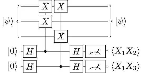
For measuring the syndrome for stabilizer $P_k$, we introduce an ancilla, apply $H\cdot CP_k\cdot H$ on it (control on the new qubit and target $P_k$ is on the encoded state), and then measure it in computational basis.

So, to measure the stabilizers $X_1X_2$ and $X_1X_3$, we need the following circuit:
Step 4: Building the Encoding Circuit
We start with the state $\ket\psi\tnsr\ket0\tnsr\ket0$. So the trivial stabilizers on this state are $Z_2$ and $Z_3$ since $Z\ket0=\ket0$. Now we need to find a Clifford operation $U$ such that,
$$UZ_2U^\dagger = X_1X_2$$
$$UZ_3U^\dagger = X_1X_3$$
We know $U$ is a Clifford operation because it maps an element of 3-qubit Pauli group to another element of 3-qubit Pauli group. This works because if $S_k$ stablizes $\ket\phi$, then $US_kU^\dagger$ stabilizes $U\ket\phi$:
$$US_kU^\dagger U\ket\phi = US_k\ket\phi = U\ket\phi$$
That means if we can find a trivial stabilizer set $S_k$, then all we need to do is find an appropriate $U$ that maps $S_k$ to $P_k=US_kU^\dagger$ by conjugation. And if we start from computational basis states, $S_k=Z_k$ is the trivial stabilizer for $\ket\phi=\ket\psi\tnsr\ket0\tnsr\ket0$.
Such an $U$ is not unique, but we can always find one. For example, $U=H_1H_2H_3CX_{12}CX_{13}$ works because:
$$\begin{align*}
UZ_2U^\dagger &= (H_1H_2H_3CX_{12}CX_{13}) Z_2 (CX_{13}CX_{12}H_3H_2H_1)\\
&= H_1H_2H_3CX_{12} Z_2 CX_{12}H_3H_2H_1 &[\because CX_{13}CX_{13}=I]\\
&= H_1H_2H_3 (Z_1Z_2) H_3H_2H_1 &[\because CX_{12}Z_2CX_{12}=Z_1Z_2]\\
&= (H_1Z_1H_1) (H_2Z_2H_2) (H_3H_3)\\
&= X_1 X_2 &[\because HZH=X\;\text{and}\;HH=I]\\
\end{align*}$$
Similarly, $UZ_3U^\dagger=X_1X_3$. You can intuitively find what $U$ should be from the relationship between Clifford gates and Pauli gates.
A concrete but naive approach can be finding out the code space first. This can be done by projecting using $\frac{I+P_k}{2}$. So, the projector to code space will be,
$$P_C = \left(\frac{I+P_1}{2}\right)\left(\frac{I+P_2}{2}\right)\dots\left(\frac{I+P_r}{2}\right)$$
Next, we can find it's spectral decomposition to find orthonormal eigenvectors corresponding to $+1$ eigenvalue. These orthonormal eigenvectors are not unique since the eigenspace is not one-dimensional. However mapping any of the eigenvectors to the computational states will give us a valid code.
For example, $\ket{+++}$ and $\ket{---}$ are one possible set of orthonormal eigenvectors for our code space. So, we can map them like this: $\ket{000}\mapsto\ket{+++},\; \ket{100}\mapsto\ket{---}$. We only care about mapping the first qubit because the other two always starts at $\ket0$. That means, any $U$ such that $U\ket{000}=\ket{+++}$ and $U\ket{100}=\ket{---}$ will give us a valid code. From there you can probably guess what circuit to choose. But of course, you need to choose your eigenbasis and mapping wisely so that it can be build only using $H,S$ and $CX$ gates.
A more concrete but involved approach is to use Gottesman-Cleve method.

![Circuit for encoding scheme of [[7, 1, 3]]](https://i.sstatic.net/peoD7.png)