note: I am unsure that you can get an answer for your question as there's not enough technical information in the paper to reproduce (for me anyway) the results. However, you could work through it in the following method for any ring oscillator.
A ring oscillator is comprised of a ring built of an odd number of inverters. The simplest model of this oscillator can be represented with a single inverting transfer function $f(\cdot)$, a delay of $\tau$ and a feedback loop that meet the Barkhausen criteria. The $f(\cdot)$ function can be approximated with a hyperbolic tangent. However, an electrical model must involve additional lumped components (low pass filter) namely the input capacitance $C$ and the output resistance R that represent inverter's active region behavior. The $RC$ is particularly pertinent due to the FPGA architecture in this case. The noise processes of the circuit are represented in the model by $N(t)$.
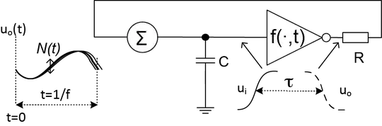
The purpose of the "PUF" in this case is to have unique delay, which is the $N(t)$. The momentary $N(t)$) value results from the sum of Gaussian noise and two-way shot noise sources (it's not thermal noise, which is actually shot noise in a semiconductor and every textbook that says otherwise is incorrect. You can derive it from 1st principles) with a zero mean value and ${\sigma^2_N}$ variance.
The ring oscillator manifests oscillations due to the propagation delay $\tau$ in delay in the feedback loop. In the image, $\Sigma$ is the contributions of $N(t)$ You then look at this behavior as non-linear delay such that
$$ \widetilde{\dot{\mathbf{U}}}_i = \frac{f(\widetilde{U},t-\tau)-\widetilde{{\mathbf{U}}}_i+N(t)}{RC},$$
where $f(\cdot)$ is the transfer function. The transfer function in this case is the PUF behavior, which the authors did not model. Also, it would be dependent on not only the semiconductor fab mismatch, but the router. The question is "does the RC of the routing contribute more than the PUF circuit variance". There's no way to know.
What they should have done is the following:
Let's assume that randomness is a function of the nondeterministic contribution of N(t) and a derivative of the random variable $\widetilde{{\mathbf{U}}}_i$. The behavior of the circuit can be explained when the random part in the above equation is omitted and a we can linearize it with a small signal model. In this case, the linearized $f(\cdot)$ function brings an amplification coefficient g, therefore, the circuit can be described with a linear differential equation as
$$\frac{d u_i}{dt} = \frac{-g u_i(t-\tau)-u_i}{RC} $$
You can then take the above and put it through a Laplace transform and find the zeros resulting in
$$ s+ \frac{1+g e^{-\tau s}}{RC}=0$$
The solution can then represented as a Fourier series with periodic responses from the time domain. You can then use these modeled for each oscillator in the chain to understand the contribution of each oscillator. For this reason, I do not believe that their analysis is adequate enough to make assumptions about the hamming distance in any method that is qualitative. It is a quantitate measurement, and I am not convinced by that paper that the authors know how their system works.
I have no idea why this paper is so highly cited. I would not pass muster in a circuits journal, and honestly, it just complicates things. You can already consider an inverter to have a unique transfer function due to surface roughness and manufacturing defects. I do not know either of the original authors, but I would love to know why this was thought to be a good idea.
 .
.