I recently bought a 10 W laser (12 V) that I'd like to mount on my old 3D printer (Geeetech Prusa I3 Pro B) and control it by adjusting the fan speed.
After reading the docs, the laser has 3 wires: PWN/TTL (3 V to 12 V signal), GND, and 12 V (aka - and +).
Here are the laser specifics:
- Model: LD3070HA (by voidmicro)
- Optical Output Power: 4 W
- Operating Voltage: 12 V
- Module Input Power: 10 W
- PWM/TTL Input: DC3.3 V-12 V 100 Hz~50 KHz Preferred: 5 KHz
- Input Interface: XH2.54-3Pin (+, -, PWM/TTL)
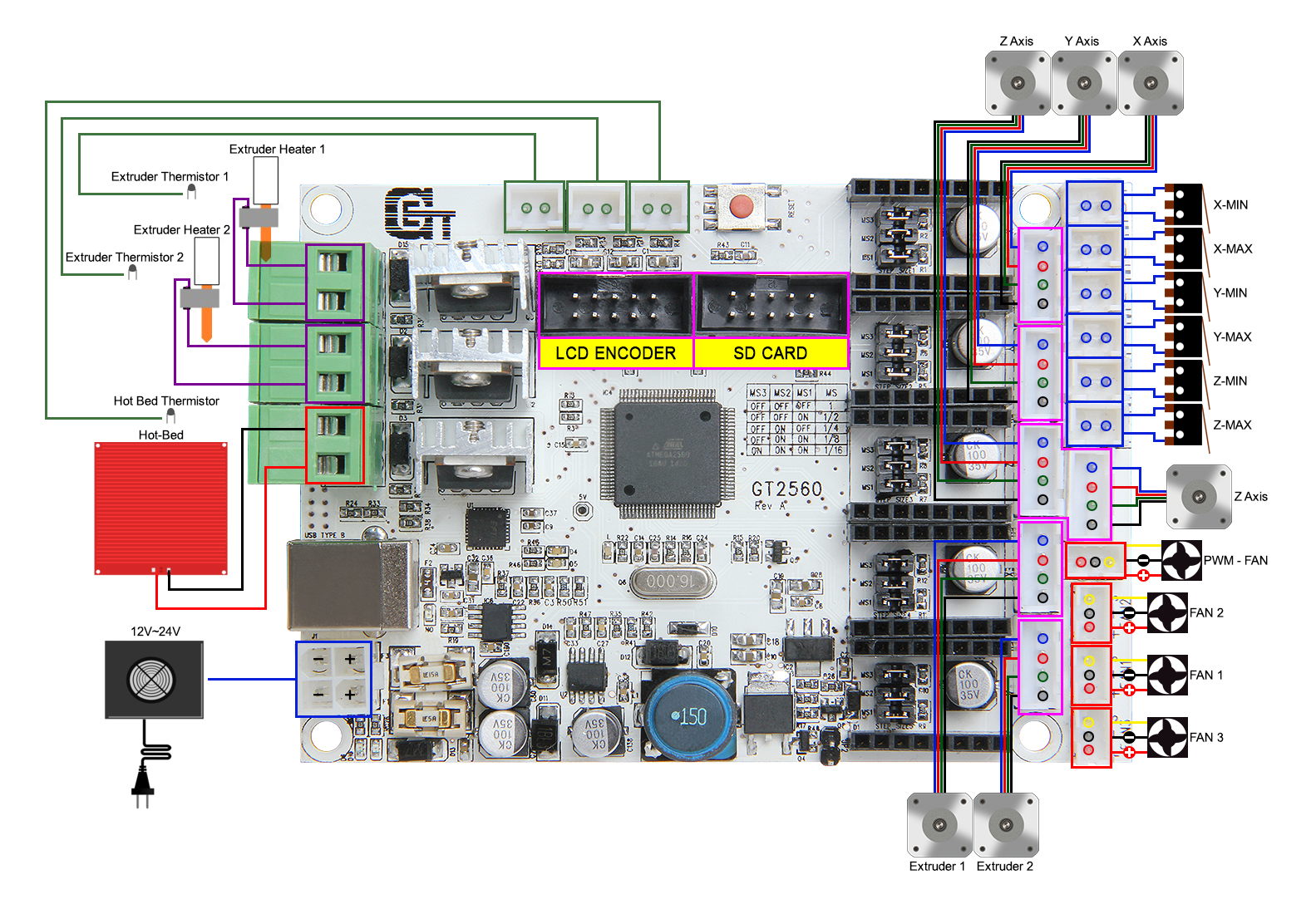
My 3D printer has a GT2560 board (docs, scheme) with a PWM FAN socket made up of 3 pins (plus, minus, and C for control I assume to return the fan rpm).
- I tried connecting the laser directly on the
PWM FAN; the laser isn't turning on (I assume not enough power since the laser needs approx. 1.2 A). - Then I tried connecting the laser
+and-pins directly on the printer 12 V power supply and thePWN/TTLyellow wire (of the laser) on the+pin (of thePWM FAN). The laser is turning on! But always at 100 % intensity (even when I turn the fan off or change its speed).
I investigated a bit. On the motherboard PWM FAN socket, I got the following voltage value between the plus and minus pins :
| Fan speed (%) | Fan speed (out of 255) | Approx. Voltage (V) |
|---|---|---|
| 0 | 0 | 0 |
| 0.004 | 1 | 5 |
| 50 | 128 | 9 |
| 100 | 255 | 12 |
I don't know if my multimeter shows an average voltage or if it is not PWM used here (even if the socket name is PWM FAN, which for me leaves no doubt...)
Potential issue: However I found out that between the + pin of the PWM FAN (on the board) and the - / ground pin (of the power supply), the voltage is ALWAYS 12 V no matter the speed of the fan!
That might explain why the laser is always at 100 % intensity and never shuts down.
I searched online and read that the grounds should always be connected together. So I tried connecting the twos minus pins (from the 12 V power supply and the PWM FAN on the board)
and. sadly nothing changed.
A few pictures to illustrate:


To be honest, I'm running low on ideas. Any help would be greatly appreciated!

