Simple Machines
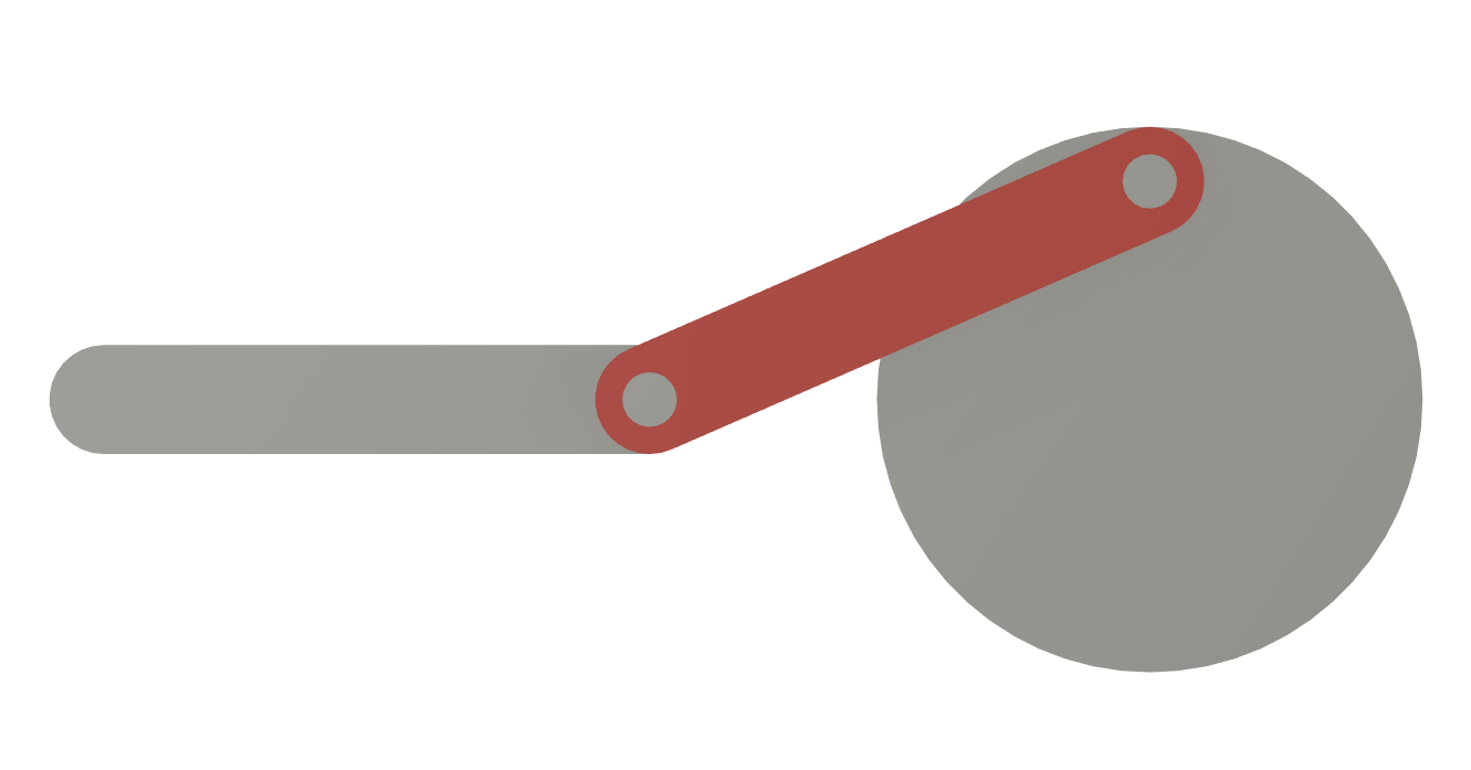
We got a circular motion, and need a linear one. The most simple set up for this is known from steam engines:

The downside is, that this is a 90° turn from the motor. But to turn a circular motion by 90° is easy: Gears.
There are many options of gear types that would work to drive the transmission disk in a right angle from the motor:
- Helical Gears engage in a 90° to one another. McMaster Carr describes them as "For smooth, quiet operation at high speeds under heavy loads, helical gears have curved teeth that engage gradually and stay in contact longer than straight teeth. Because the curved teeth create thrust loads (loads that are parallel to the shaft), helical gear systems often require thrust bearings to prevent wear from misalignment."
- Miter Gears have their teeth mounted on a cone. There are 2 types (normal and spiraled), and McMaster Carr describes them as "Miter gears have straight teeth and a conical profile for transmitting motion at a right angle without changing shaft speed or torque. They're more efficient than spiral miter gears, which means they require less power to do the same work; however, they are noisier when run at high speeds and under heavy loads."
- Very similar are Beveled Gears, but the tooth geometry is simpler. McMaster Carr says: "Similar to miter gears, bevel gears have straight teeth and a conical profile for transmitting motion at a right angle. Unlike miter gears, one of the gears (sometimes called a pinion) is smaller than the other."
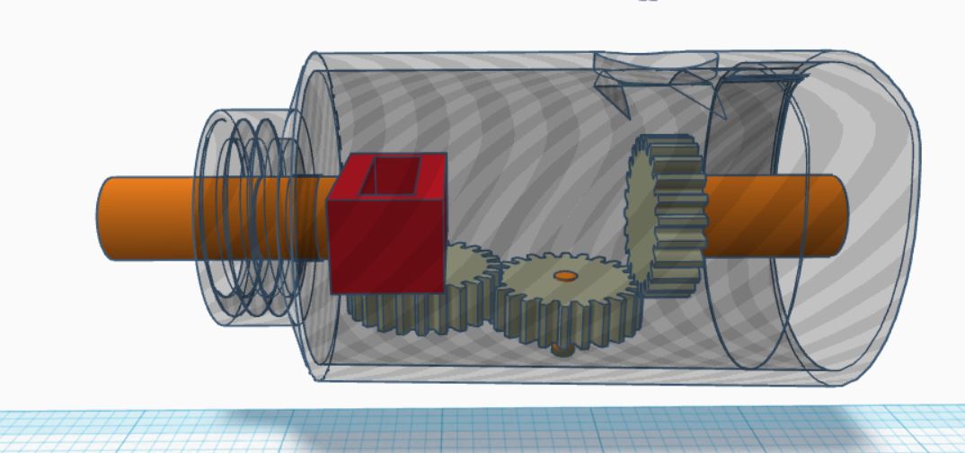
- The outside of the disk is connected to a worm gear. The linear motion will be slow but VERY powerful, and the machine can't drive the motor. McMaster Carr says: "Worm gears use screw threads to reduce shaft speed by ratios of 18:1 and greater while transmitting motion at a right angle. Unlike bevel gears, worm gears operate in one direction only; they transmit motion from worm to gear and cannot be reversed."
Redesigning the original part: the Angled plane in motion
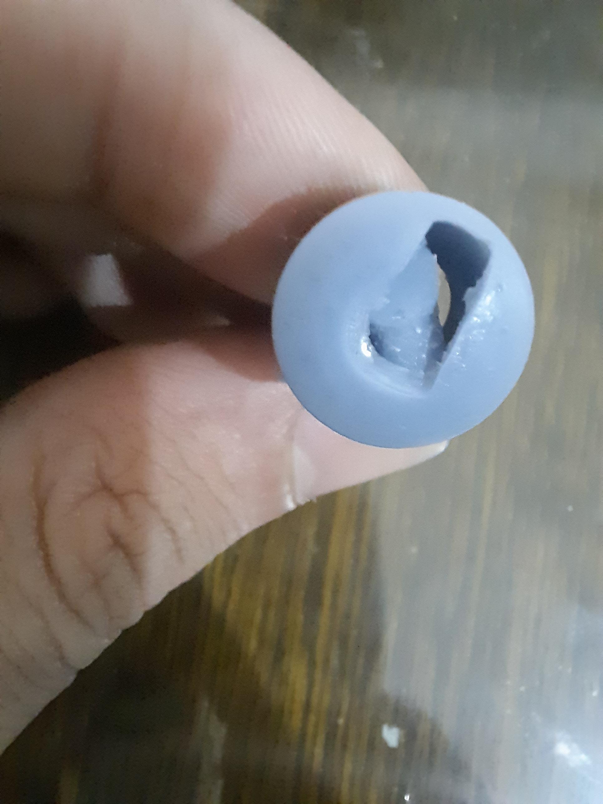
Your basic idea works but your design had two large problems:
- The alignment feature for the pushrod is way underdesigned
- The Pushrod is missing a secondary alignment feature
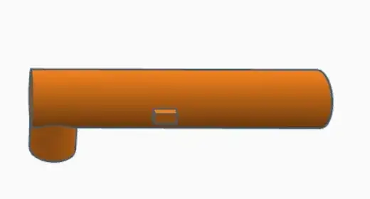
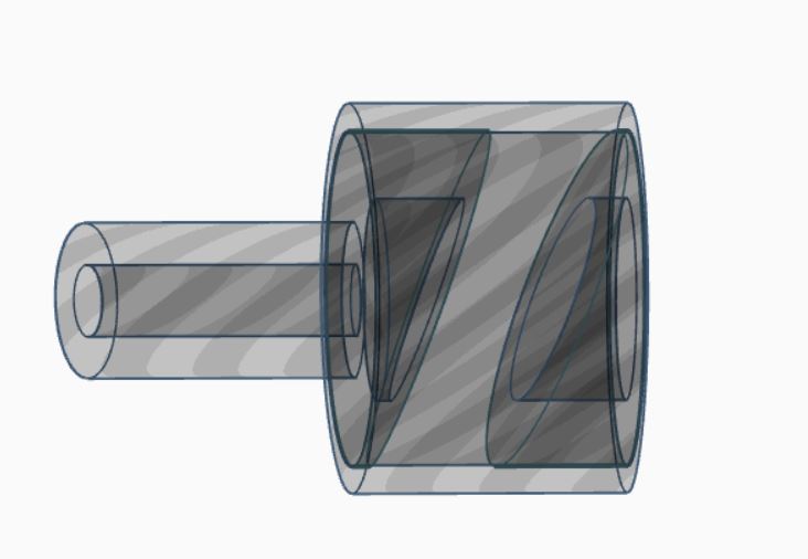
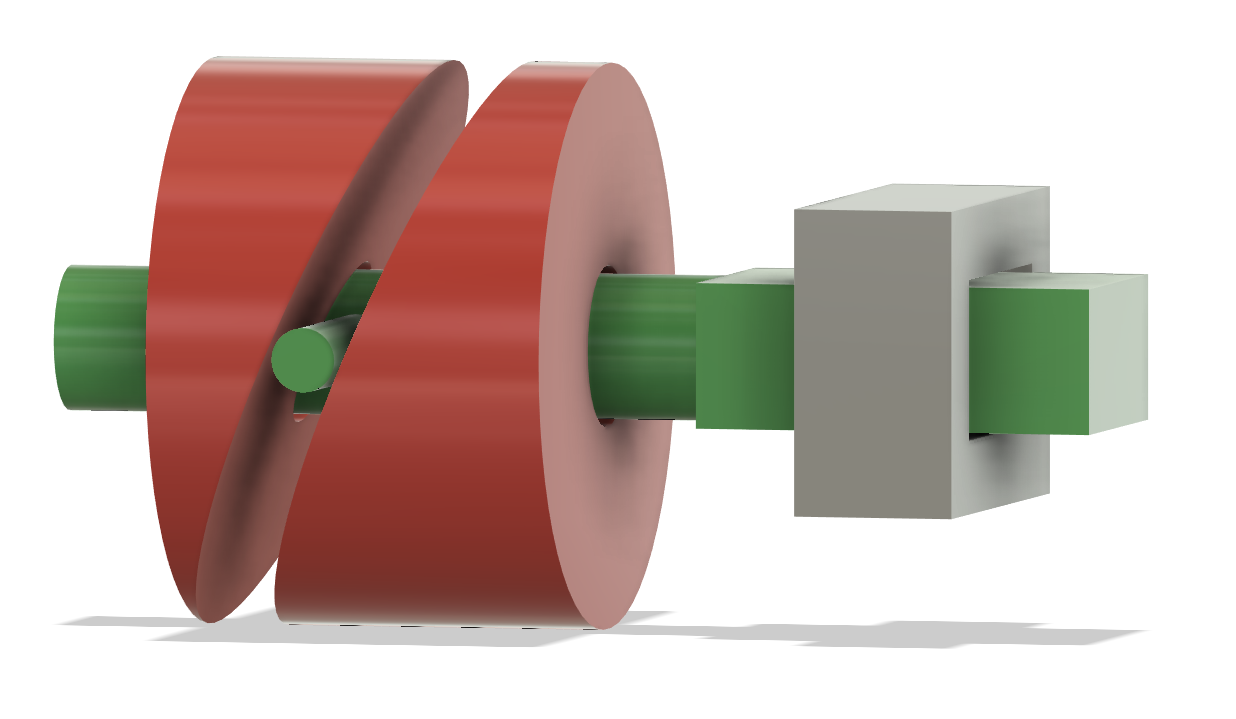
That is easy to solve, and reduced to the working areas, this is what might appear in your construction, approximating the actually very complex surface to an angled face:
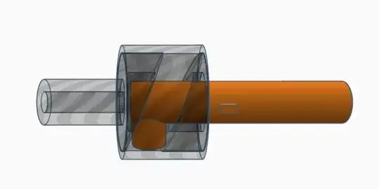
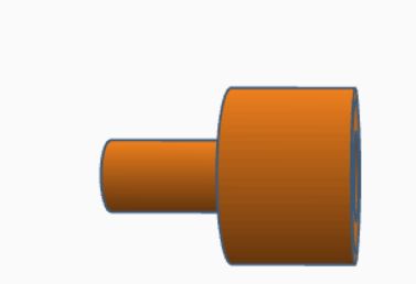
The rotating angled plane is good to act. To prevent rotation of the green pushrod, I made the retainment lugs much beefier and part of the whole shaft, not an addition onto the shaft. That made it a large rectangle, which prevents any rotation in the grey housing part.
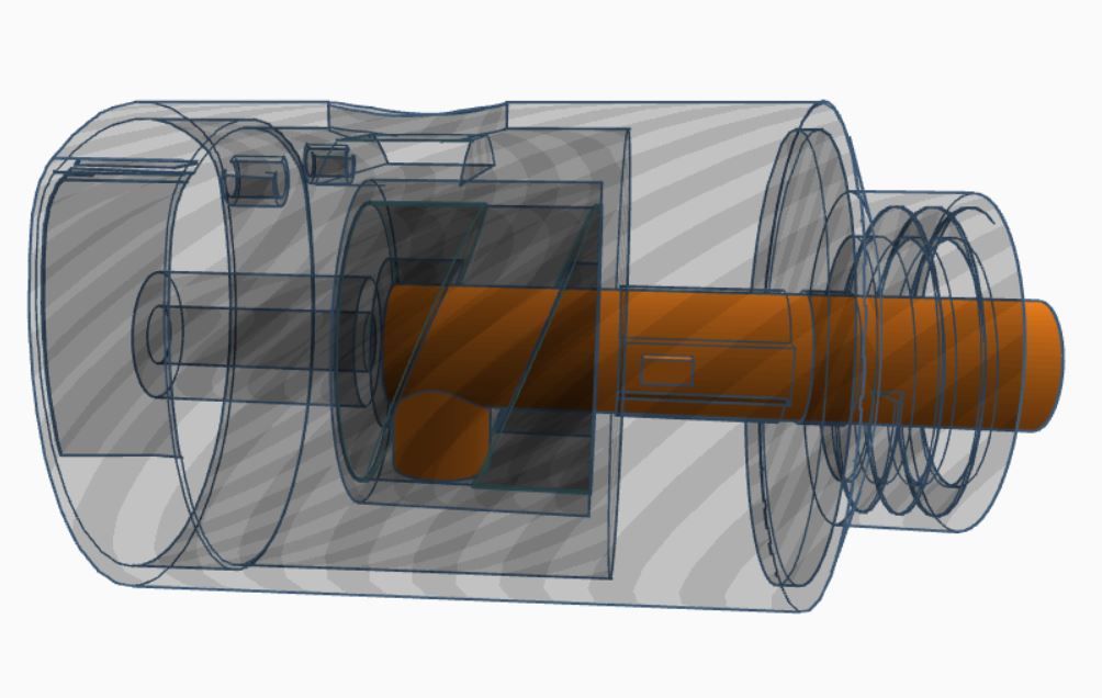
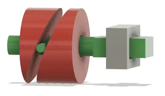
Do note that the rendition as a simple ramped cylinder is just a very rough approximation of the actual body you need, which would be the rotational cut of a rotating and sliding cylinder. The required cam track can be quite tricky to design in CAD.
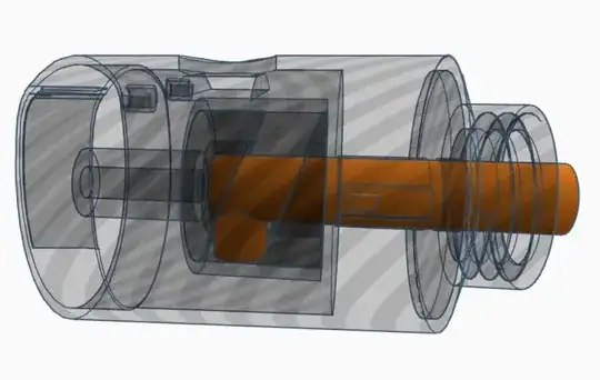
The shaft also protrudes through the bottom angled surface in the most forward position, which prevents the shaft from misaligning at that critical point and not hitting the bore it has to get back into. This protrusion can be much shorter than shown, but it is very much aiding in reliability and preventing the misalignment you saw.
As an additional factor, the turning disk might need to be made from two halves that are connected, so it can be put around the shaft and not contain an insert-slot that would result in misalignment. You might need interlocking pegs between the parts of the rotating barrel to force alignment.
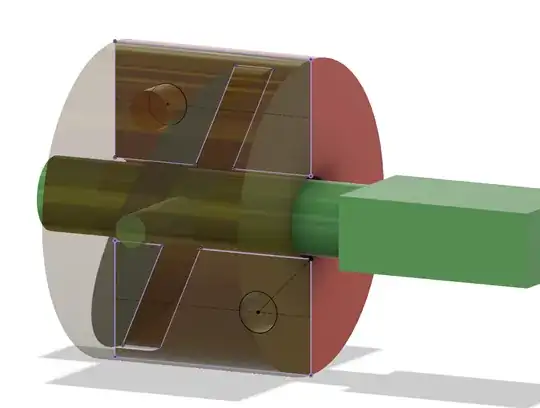
However, there's one problem with the design in itself: the setup has very large contact areas and will induce lots of friction.