By connecting to the D9 output header (see RAMPS 1.4 shield schematic below) you only have 2 wires that represent a scheduled load and ground. You actually need to connect the positive (red) lead to the power supply 12 V and the negative (black) lead to the ground. The third wire (usually a different color) needs to be connected to the actual D9 in your example; note that this one is connected to the MOSFET! And as such not readily available, it is far more easy to use an other free pin.
Just use the PWM pin (attached to the MOSFET) of the print cooling fan (that schedules the MOSFET), you can then schedule the laser power with G-code M106, e.g. M106 S127 to select half the power (S255 would be max power). Alternatively, and probably a much better solution is that you can use any free (but exposed) pin of your microprocessor; you can set the value of that pin using G-code M42.
M42 switches a general purpose I/O pin. Use M42 Px Sy to set pin x to value y, when omitting Px the LEDPIN will be used.
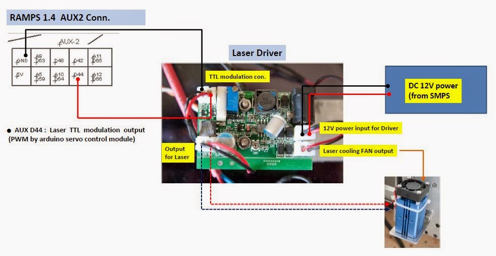
The only electrical wiring you need to do is to attach a wire (solder or connect to a header) to bundle that with a power and ground wire and route that to the laser module.
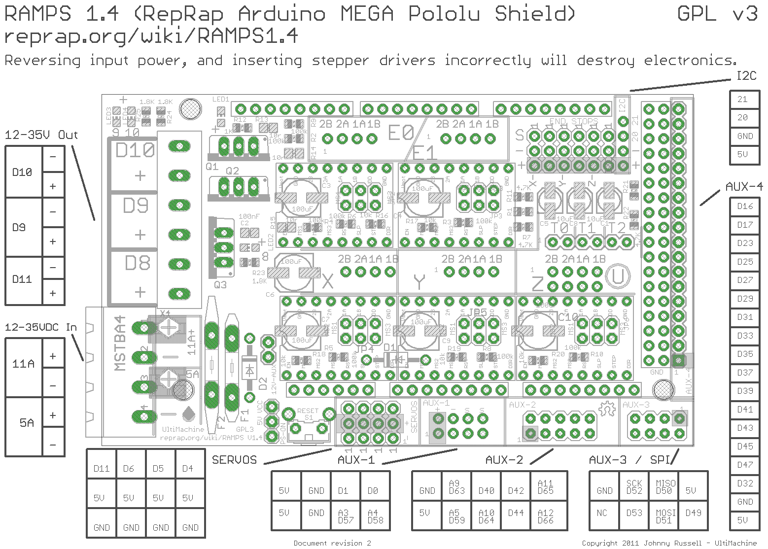
Note that the PWM pins of the Mega are numbered D2 through D13. Also, D44, D45 and D46 are also PWM capable. Checking the RAMPS 1.4 (the board/shield of the Reprap Guru) pinout, you will see that D8, D9 and D10 are used for the MOSFETs (and as such not easily available and would require soldering). E.g. D2 and D3 are used by the X max/min endstops (note that most printers don't use an X-max, so pin D2 may be free on your machine).
For your purpose, any of the following pins can be used: D2, D4-7, D1112-13 and D44-46.
Best option would be the D11 pin (on second thoughts, D4 might be a much better option as the timer associated with PWM on pin D11 is internally used in Marlin for generating interrupts); it has a pin you can connect to the SERVO header pin.
The image shows the location of the pins:

An example to connect a laser module is seen in this image: